1 / 5
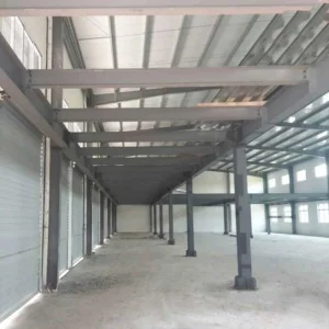
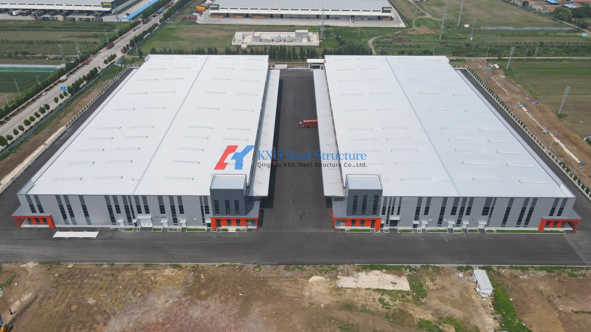
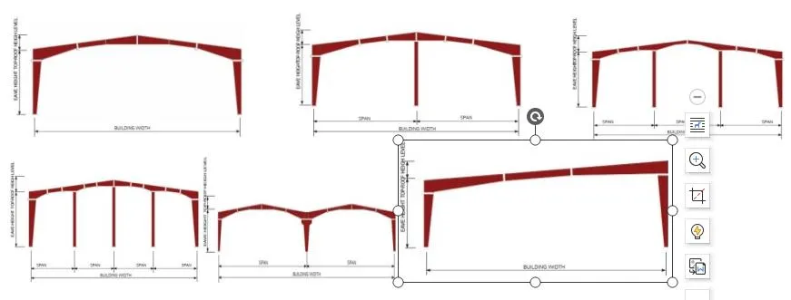
Pre-engineered steel buildings are structural systems designed and fabricated based on a structural concept of primary members, secondary members, roof and wall sheeting connected to each other, alongside various other building components.
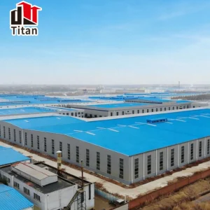
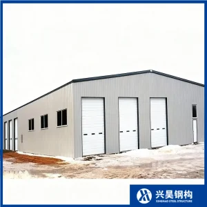
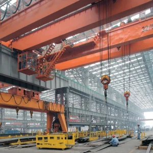
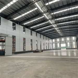
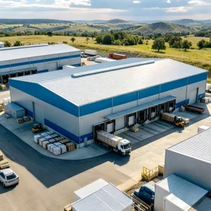
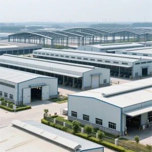
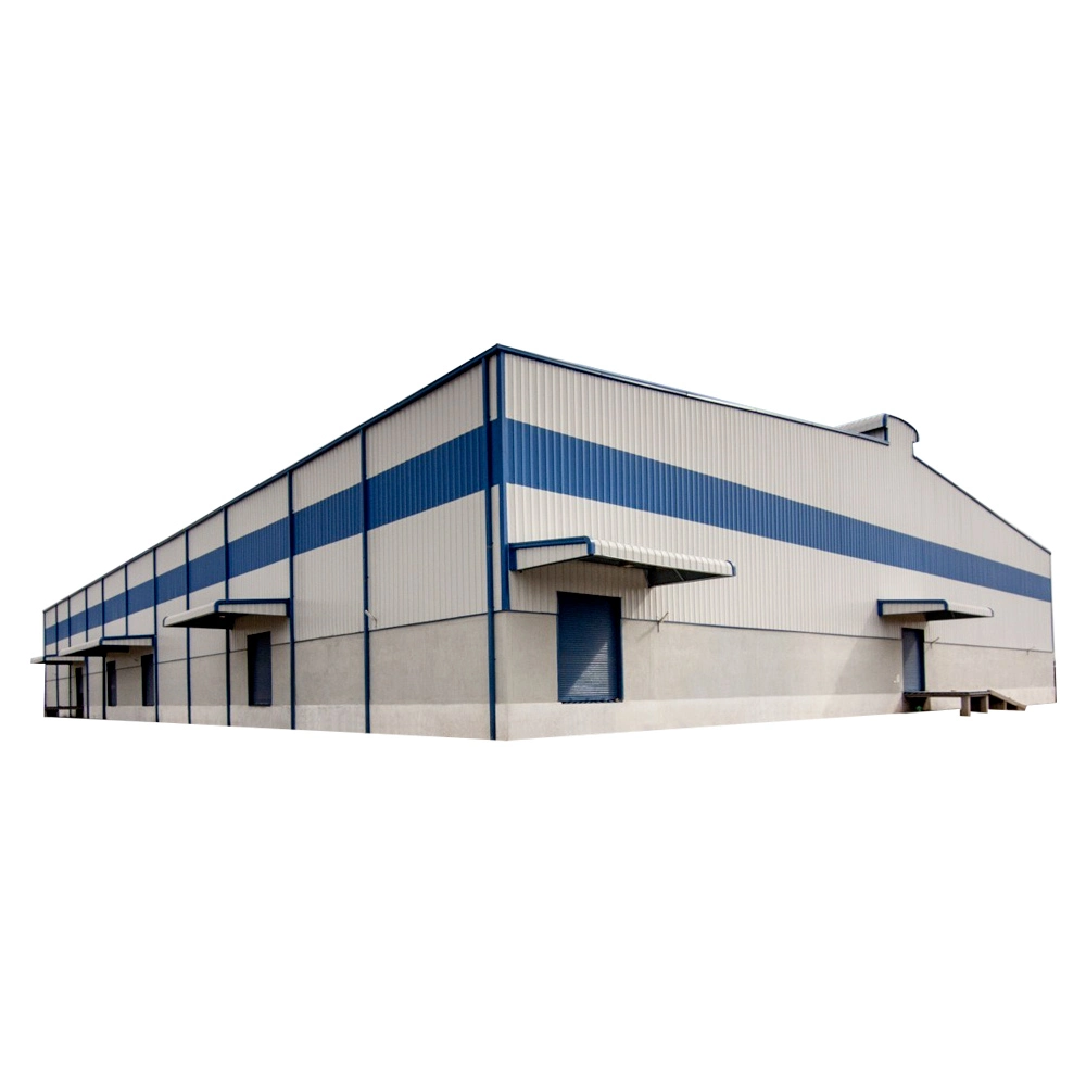
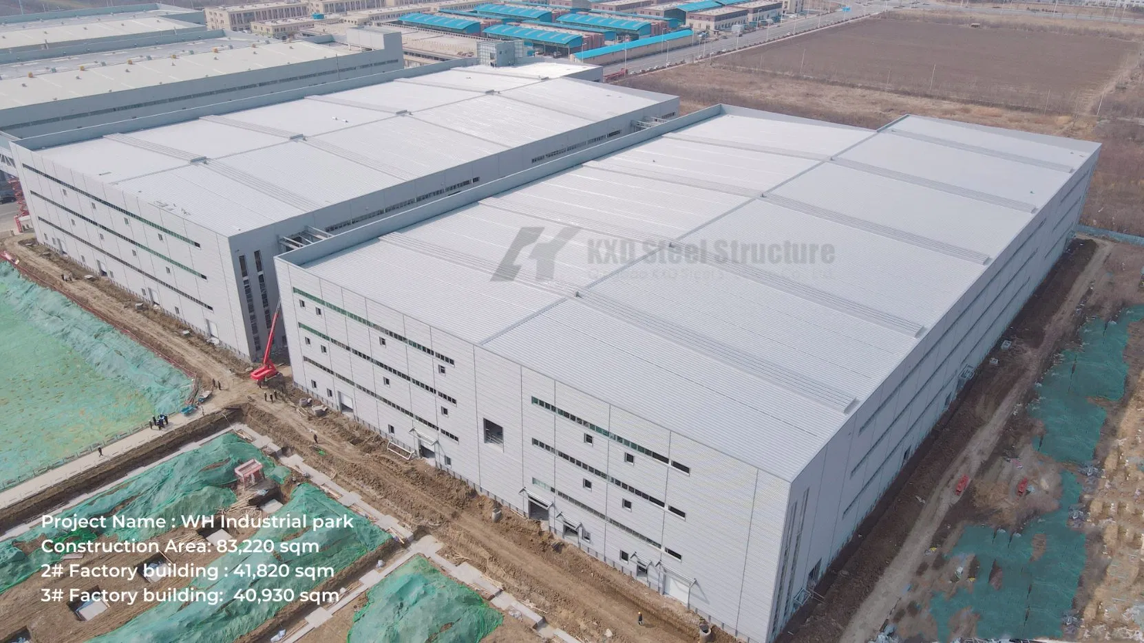
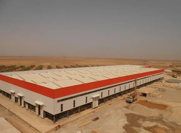
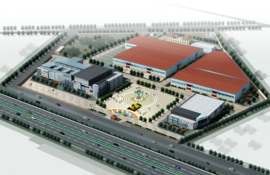
Pre-Engineered Buildings (PEBs) provide flexible solutions for contractors and developers. Featuring low cost, high durability, strict quality control, and rapid erection, PEBs are utilized across diverse applications:
Price per square meter can be 25% to 30% lower than conventional steel buildings. Site erection cost is reduced due to faster installation times and simplified assembly processes.
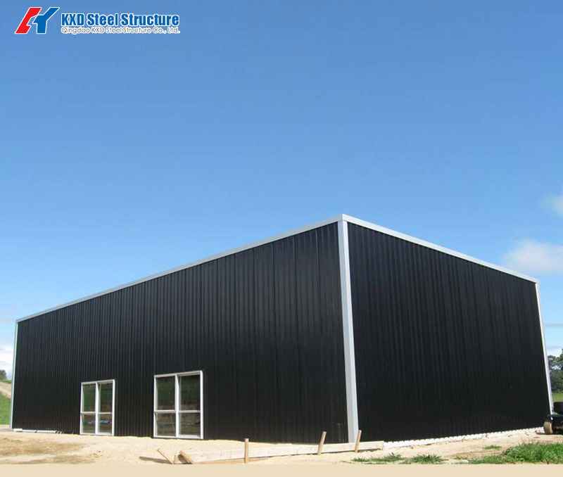
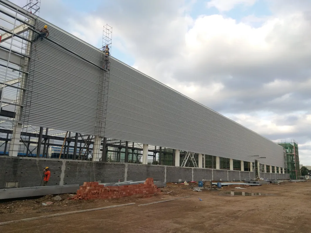
All steel components are fabricated at the factory and connected with bolts on-site. Erection is fast and requires basic equipment. This results in up to 60% less construction time compared to traditional reinforced concrete (R.C.C.) buildings.
PEBs are highly adaptable to design modifications, easy to expand for future needs, and highly economical to transport.
Pre-engineered buildings serve as an eco-friendly solution featuring lower carbon footprints, high energy efficiency, and full recyclability.
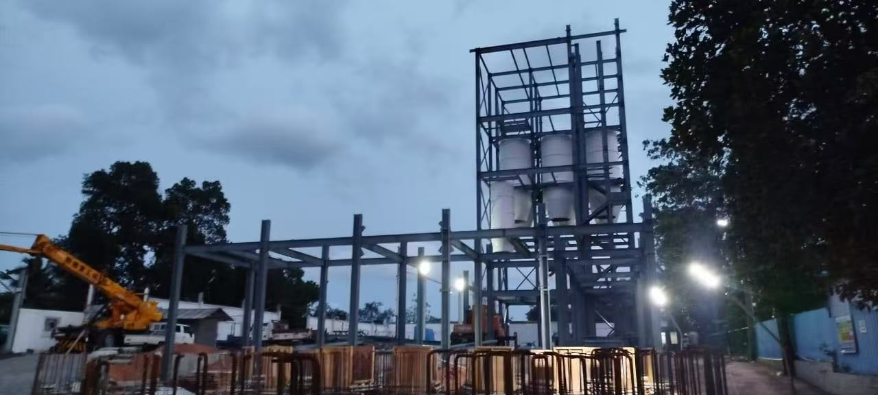
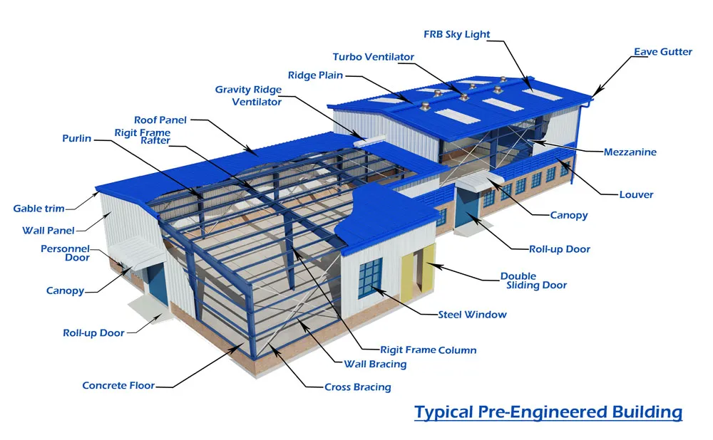
Pre-engineered metal buildings consist of the following integrated systems:
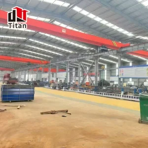
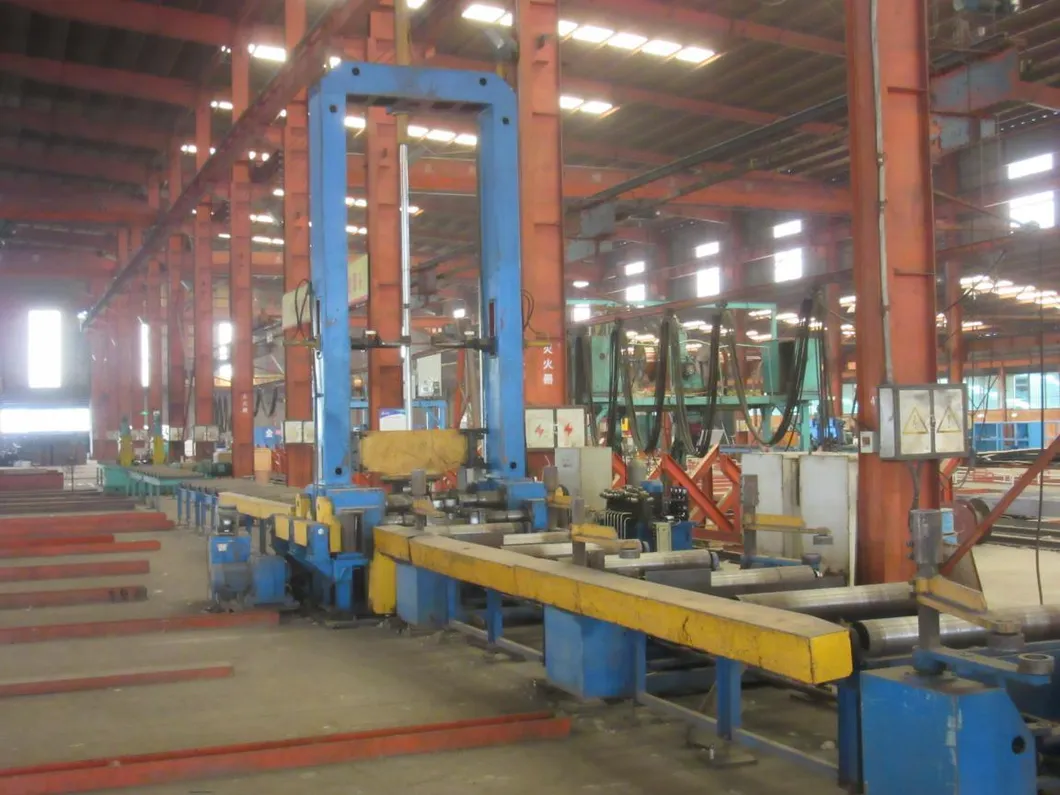
The manufacturing process ensures clean guidelines and methodology during the fabrication, blasting, painting, and supply of pre-engineered structures.
Verification of receiving documents, quantity, and visual inspection of incoming raw material is conducted. Dimensional checks are done to confirm precise geometry (length, width, depth, thickness). Heat numbers are verified against Mill Test Certificates (MTC) to guarantee traceability.
Engineering drawings are converted into NC files for automated machining. For plates: CNC automated processing executes marking, drilling, and plasma cutting. For beams/tubes: Drawings guide automated cutting and drilling before transfer to the fit-up section.
Fabricators align and fit parts, including end plates, gussets, stiffeners, and purlin cleats, based on shop drawings using tack welding, subject to QC verification.
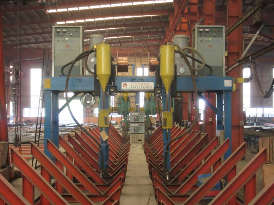
Qualified processes like Submerged Arc Welding (SAW) and MIG Welding are utilized. Joint areas are cleaned of contaminants. Fillet weld sizing strictly adheres to design tolerances and standard specifications like GB50661-2011. Grinding is done to remove spatters, slag, and sharp burrs.
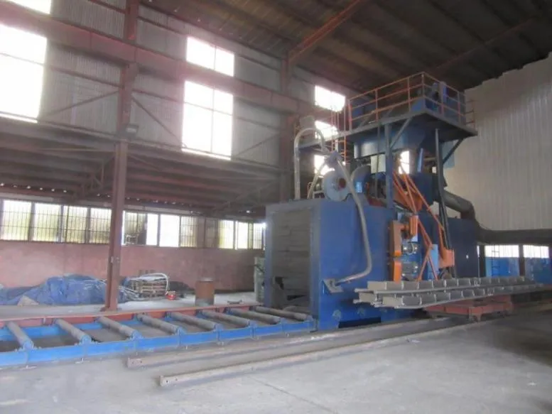
Automated shot blasting cleans the structural steel surfaces to Grade SA 2/2.5. Debris is cleared via high-pressure air before moving to the coating phase.
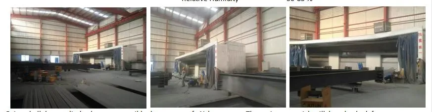
Coating applications proceed under monitored atmospheric controls (Air Temp 5-40ºC, Substrate Temp 23-40ºC, Relative Humidity ≤ 85%). Standard systems feature airless spray application, checking Wet Film Thickness (WFT) during application to hit the dry film targets (Primer, Second, and Finish coats per project spec).
Finished components are carefully stored and shipped in secure, seaworthy packaging to prevent transit damage.
Strict quality protocols align with international design and fabrication codes including ISO9001 and CE standards. Key specifications strictly followed include:
Defines rules for weld geometry to guarantee load capacities. Minimum fillet weld size is calculated via K ≥ 1.5√t, where t is the thickness of the thicker member.
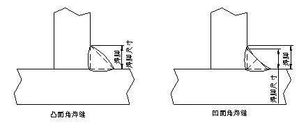
| Form of Fillet Weld Leg | K (Fillet Weld Size) Value | Application Notes |
|---|---|---|
| Fillet weld without groove | K = (0.7 ~ 1)t and ≤ 15mm | Standard structural steel buildings |
| K = (0.5 ~ 0.6)t | Strengthening ribs and secondary members | |
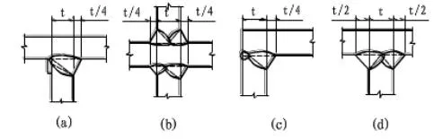
| Fillet weld with groove (CJP/PJP) | K = t/4 and ≤ 10mm | Standard structural joints |
| K = t/2 and ≤ 10mm | Critical members (crane beams/connection joints) |
| Parent Metal Thickness (t) (mm) | Minimum Fillet Weld Size (mm) |
|---|---|
| t ≤ 6 | 3 (5 for crane beams) |
| 6 < t ≤ 12 | 5 |
| 12 < t ≤ 20 | 6 |
| t > 20 | 8 |
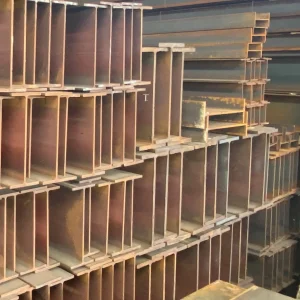
Main structural H-sections are manufactured via an integrated processing sequence: cutting, assembly, automatic welding, flange strengthening, blasting, and painting.
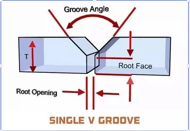
Specific bevel configurations (CJP, PJP, backing material types) are designed based on base metal thickness and welding methods to reduce weld filler volume, ease slag removal, and limit deformation.
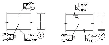
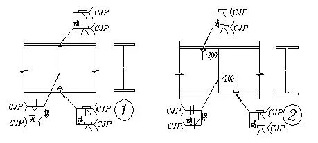
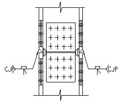
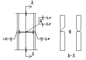
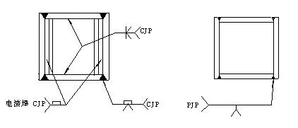
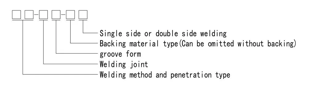
| Mark | Welding Method | Penetration Type |
|---|---|---|
| MC / MP | Shielded Metal Arc Welding | CJP / PJP |
| GC / GP | Gas Shielded / Self-Shielded Arc Welding | CJP / PJP |
| SC / SP | Submerged Arc Welding | CJP / PJP |
| SL | Electroslag Welding | - |
Design loads and calculations strictly comply with the following latest international building codes:
| Deflection Type | Type of Structural Members | Deflection Limitation |
|---|---|---|
| Vertical Deflection | Portal frame rafter (supporting corrugated sheets and cold-formed purlins only) | L / 180 |
| Rafter with ceiling system | L / 240 | |
| Rafter with top running crane | L / 400 | |
| Mezzanine Deflection | Main beam | L / 400 |
| Secondary beam | L / 250 | |
| Lateral Deflection | Wall panel | L / 100 |
| Wind columns or wind truss structures | L / 250 |
| No | Components | Specifications | Min Yield Strength | Design Code |
|---|---|---|---|---|
| 1 | Built-up Plates | GB/T1591-2008 | Fy = 34.5 kN/cm² | CISA - Latest Edition |
| 2 | Hot Rolled Beams | GB/T11263-2010 | Fy = 23.5 kN/cm² | CISA - Latest Edition |
| 3 | Cold Form Galvanized | GB/T 2518-2008 | Fy = 45.0 kN/cm² | CISA - Latest Edition |
| 4 | Roof/Wall Panels | GB/T12754-2006 | Fy = 34.5 kN/cm² | CISA - Latest Edition |